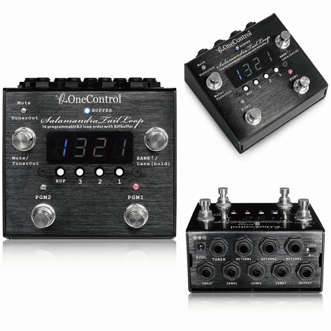
Salamandra Tail Loop
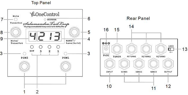
(1) PGM1/PGM2
The two footswitches recall program 1/program 2 stored in the memory.
Press again on a recalled program will master bypass the switcher.
(2) Programmer buttons
These are programmer buttons, 1", 2", 3 are to edit the order of the loops,
“1" “2" ”3" represent the positions in the signal chain,
"BUF" is to on/off the BJF buffer circuit. Check the detail in the programmer section.
(3) PGM indicator
Programindicator, it lights up when a program is recalled.
(4) LOOP display
The display show the connection order of active loops.
(5) BANK switch
The switch scrolls up the bank number by short pressing, or hold this switch for 2s
to change the memory lane (see section 6).
(6) BJF buffer indicator
The indicator lights up when the BJF buffer is on.
(7) MUTE indicator
The indicator lights up when the switcher is muted.
(8) MUTE switch
The switch mutes the output, at the same time connects “Input” jack to “Tuner” jack.
(9) BANK/BUFFER display
When press the BANK switch, it shows the bank number.
When a program is recalled by press PGM1/PGM2, it shows the buffer setup for 2 seconds,
then it turns to show the current bank number.
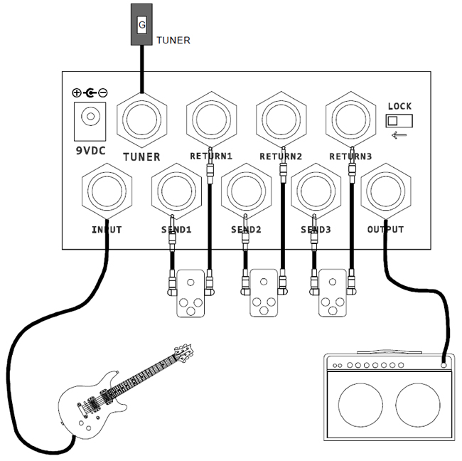
(10) INPUT
Connect guitar here.
(11) SEND jack of loop
Connect this jack to input of guitar pedal.
(12) OUTPUT
Connect the jack to amplifier or other instruments.
(13) LOCK
The programmer buttons will be disabled when the toggle switch is at the lock position.
(14) RETURN
Connect this jack to output of guitar pedal.
(15) TUNER
This jack internally connects to input jack when MUTE switch is engaged, normally it
connects to a tuner.
(16) 9V DC
5.5x2.1mm type, connects to negative center DC 9V/300mA power supply.
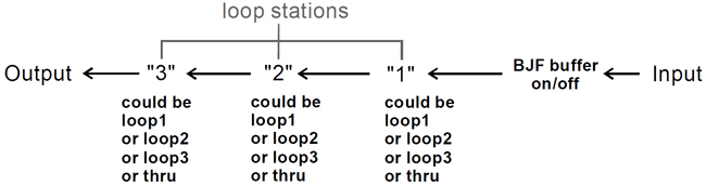
SARAMANDRA Tail Loop allows to change the connection order of guitar pedals.
Guitar signal is fed to the input jack, goes into BJF buffer circuit, then it is posted
to loop stations "1" "2" "3" in sequence, each loop station could be set to loop1 or
loop2 or loop3 or thru, each loop can only be used once in the loop stations.
ㅁ Edit Programs
16 editable programs are stored in 8 banks, they can be recalled
by pressing PGM1/ PGM2 switch. Each program have two status
- recall/bypass, step on an recalled program will toggle to bypass.
The program is editable only when a program is recalled
(PGM indicator lights up). Each loop station (1/2/3) can be
assigned with loop1/loop2/loop3/through by pressing the under
buttons, each loop (loop1/loop2/loop3) can only be assigned once
in a program, see section 4 for more details of loop code.
Edit the buffer by pressing the "BUF" button, the buffer could be on/off even in bypass status of a program, see section 5 for more details of buffer code.
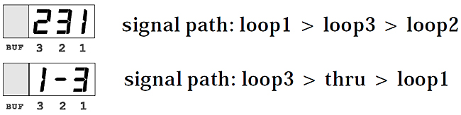
ㅁ Loop Code
The loop code shows the active loops and connection order.
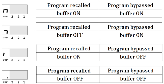
ㅁ BJF Buffer and Buffer Code
The BJF buffer is a post buffer which is in front of all the loop stations.
the BJF buffer could set to turn on/off in both status (engage/bypass) of a program, the buffer code shows the on/off setup in each program.
ㅁ Bank
Saramandra Tail Loop have 8 banks in 2 lanes, each lane have 4 banks (1~4). Press BANK switch will scroll up the bank number, the bank number blinks till a program is recalled. Hold the BANK switch for 2 seconds will change the lane and the display will have an extra “dot” under the bank number.
ㅁ Mute / Tuner
Press MUTE switch will mute output, at the same time connect the INPUT jack to TUNER jack, press the MUTE switch again will cancel the mute.
ㅁ Specifications
Dimensions....................................115(W) x112(D)X70(H)mm
Weight...............................................................................500g
Power Supply......................................................................DC9V
Current Drain...........................................................max. 160mA
Input impedance.......................................................... 500K ohm
Output impedance..........................................................10K ohm
ㅁ Typical Connection